Tag: hardware
2012
05.17

A while ago I read this excellent article by Evil Mad Scientist Laboratories describing the need for some form of visual diff tool for open hardware projects. I had been thinking this was a great idea, but while working on a recent project, decided to actually start implementing something. I use the gEDA suite of tools, so that is what I’m creating this for, but the majority of the plumbing should be reusable for other file formats.

The first piece of this puzzle for me was automatically making image files of my schematics and PCBs that have changed and adding them to each commit. GitHub has image diffing capabilities built in, so this works great. I implemented this a pre-commit hook in .git/hooks/. My git hooks can be found here. I have designed them to work with the git-hooks tool by Benjamin Meyer.

This script seems to work fine for me, though I’m open to suggestions for improvements. My major issues with how the hooks work (which are more issues with git than my hook) are

  1. The status message in the auto-generated commit comments is not being updated with the new image files and
  2. Hooks don’t get pushed into remotes

The first issue feels like a bug to me, but I suspect that it was done intentionally for some reason I’m not aware of. I have played with a work around by adding a prepare-commit-msg hook that just regenerates the commit message comments, but I have tested the pre-commit hook enough that I don’t feel I need to be aware of the addition of the images.

The second issue I am told is a security issue as it would cause arbitrary code to be executed on the machines of others who might clone (and possibly even the server). One nice feature of the git-hooks tool is that it can use hooks in a local repo directory, so if you include my scripts in the git_hooks repository, you just need to run ‘git hooks –install’ and you will have the hooks working. Without that tool, you can just manually copy them into the proper file in the .git/hooks/ directory.

This method works well if I want to view visual diffs online, but sometimes I might be offline or perhaps I just don’t want to push my project to a public GitHub repo. For that, I plan to make some simple scripts that call visual diffing tools on my local repository. Git has the capability to set your git diff tool, so my plan is to write a wrapper script that picks the right tool based on file types. This script might also generate an image from files that cannot be diffed directly and don’t have the above auto generated files

Edit: Of course not 20 minutes after I publish this post I discover schdiff, a tool bundled with gEDA since the start of 2012 that is designed to hook into git-difftool to provide a visual diff of gschem .sch files. One format down, some more to go.  :)

Edit 2: Less than a day later and I discover there is also a pcbdiff tool on my computer that came with gEDA pcb. In Arch Linux, it installs to /usr/share/pcb/tools/pcbdiff, but it is not in the path, so in my .bashrc I just added ‘export PATH=”$PATH:/usr/share/pcb/tools”‘ at the end. I feel pcbdiff outputs images that are too low a resolution, plus it can’t handle when the .pcb files change in physical size, so I might submit a patch or two. Long story short, now I just need to make a script that auto-calls these diff tools based on the file type.
2012
01.15

Photo by Wi Bing Tan

A little over a year ago I posted about switching back to the Dvorak keyboard layout. I have stuck with it since then and that is pretty much all I have used. I thought that I would give a quick update as to how that is going and what else is going on in my keyboarding life.

Read More >>

2011
08.17

NES-chuck Demo from Benjamin Bergman on Vimeo.

I finally got around to making a quick demonstration of my NES-chuck. Code for the NES-chuck can be found here. The future event I mention is ArtCadia, which is part of Nuit Blanche. I’m not yet sure if I (or the NES-chuck) can attend, but I will keep this updated.

After the break, there is a rough draft of my script for the video.

Read More >>

2011
04.02

Last Sunday, UMIEEE together with UMARS (two University of Manitoba student groups I am a part of) got together to hold an embedded systems workshop on campus. We helped teach a bunch of fellow students the basics of designing and programming embedded systems. We used TI’s MSP430 Launchpad development kit, a super low price dev kit, so that everyone could go home with their project and continue experimenting. While the Launchpad (or rather the MSP430 microcontroller on the board) isn’t as easy to program as something like an Arduino, the Launchpad allowed us to convey some of the more fundamental principles of embedded design like bit masking and timer interrupts.

The morning consisted of getting the tools setup and getting a “hello world” application running. The official tools are Windows only, but the Launchpad does work with Mac and Linux once you figure out how to install everything. It actually seemed to work better, due partly to the fact that the tools are open source and hence not crippled versions of paid software, but also because the environment was less integrated (ie you use a text editor, a compiler, and a debugger all separately instead of a full blown IDE like they use in Windows). The Windows users ofter had to restart the whole IDE when one part of the system locked up for unknown reasons.

After lunch, we dove into making a much more ambitious project: an LED chaser. The design specifications we gave to everyone was something to the effect of “when you press a button, your chain of LEDs will light up one by one until you reach the final one in the string.” The idea was then to replace the final LED with the next person’s button input pin and watch as the lit LED ran across everyone’s boards. The day before, the volunteers leading the workshop got together and pumped out a quick (and admittedly buggy) code for this, so we felt it was an attainable project. We nudged everyone along, showing them how to light individual LEDs, use interrupt pins and timers, and wire up buttons with pull up resistors. I think only a few people actually got the final chaser working, but everyone had a good time.

You can see an abstract for the event along with a bunch more pictures here.

2011
01.25

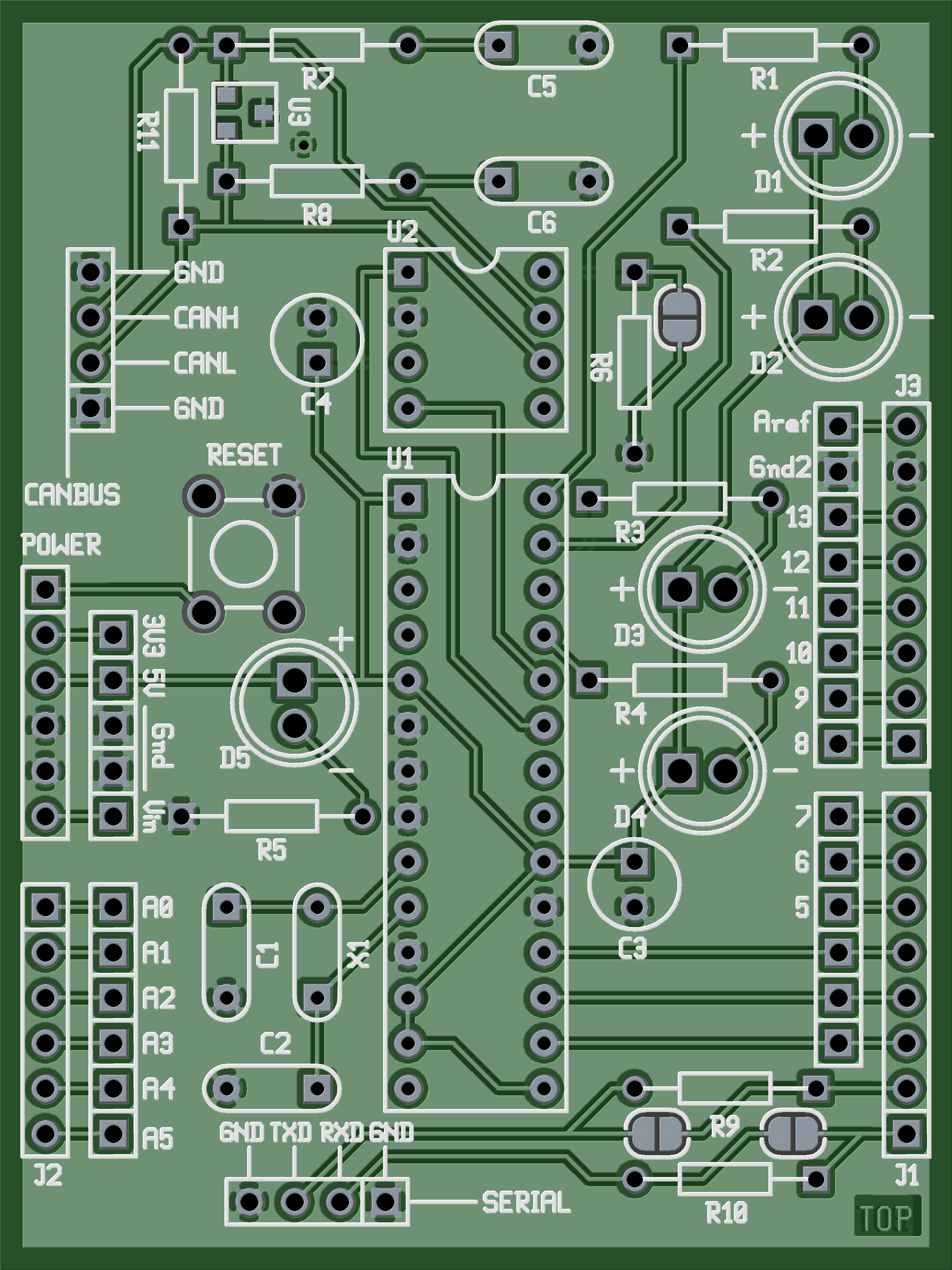
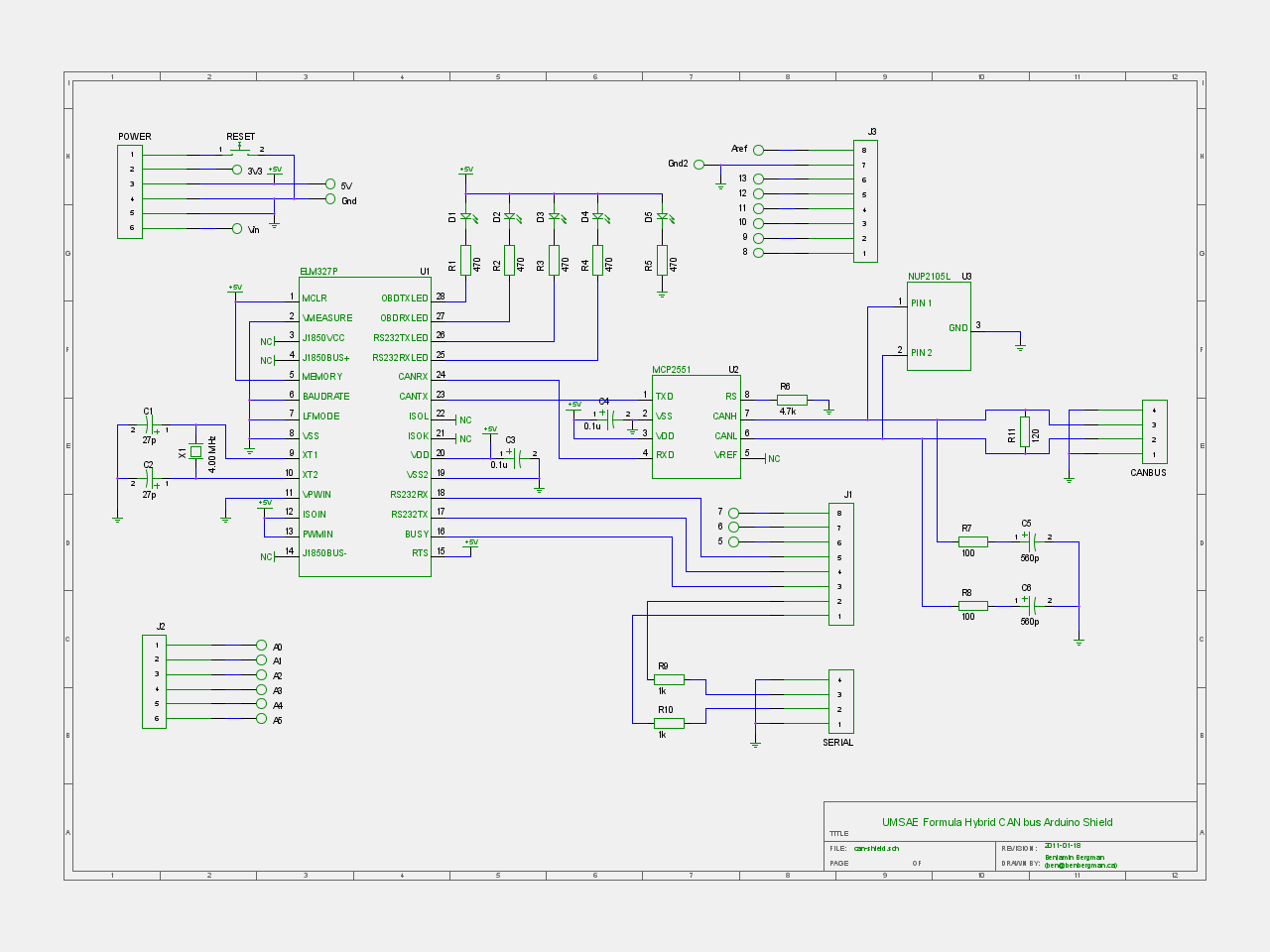
As some of you are aware, I am a member of the University of Manitoba SAE (Society of Automotive Engineers) Formula Hybrid team. The major project that I have been working on for a while now is a CAN bus controller Arduino shield. The system is based on the one designed by Mike Sefton last year. We are using the same CAN interpreter because the manufacturer was generous enough to donate some chips to us. These chips work well, but they are designed to be used with an OBDII reader, so we are using a few work arounds to get the system to work for us the way we need.

Aside from some simple changes to the circuit, there are two major changes to the system. First, I added a the NUP2105L chip to the CAN bus to give us some over-voltage protection. The major cause of failure last year was over-voltage, which is always a concern when dealing with electric vehicles. The second change was to allow an outside system to communicate with the CAN controller over a serial connection. Last year the CAN devices were controlled directly by the Arduino, but this year the Arduino is basically a middle man that can do some processing of commands if needed.

For the hardware design, I decided to try out a few open source tools. I first tried KiCad because it was more cross platform and a fully integrated suite. There were some things I didn’t like about it though (although I may have just been looking in the wrong place for the feature I thought was missing) so I decided to try out gEDA. I personally liked the feel of gschem better than KiCad’s schematic editor, and the PCB software seemed quite good to me too. The workflow between tools is a bit less intuitive, requiring a few terminal commands, but I am quite comfortable with the command line, so I can see myself using gEDA much more in the future.

The files for the hardware design are posted here: HARDWARE

The firmware for the Arduino is posted here: FIRMWARE

The firmware is currently a very basic repeater but will likely see changes once we start figuring out what specific features we will need. Feel free to post a comment or send me an email if you have any questions about the design.