2012
08.01

A few weeks ago I was hanging out at SkullSpace and a group of fellow makers were working on their Arduino controlled hi-fi setup. They already had all the hardware for the setup constructed and were working on the interface when they realized that a soft-shutdown mode would be useful for saving state. Unfortunately, the power controller in the system just cuts power to the transformer that provides the Arduino 5 volts. We figured out a solution to this problem and I thought it was pretty clever, so I thought I would share it.
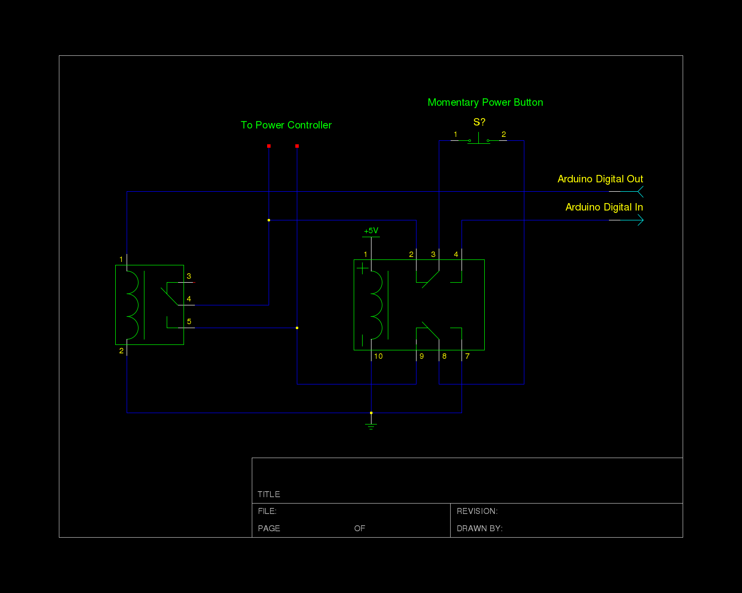
The power controller module used in the system takes input directly from a momentary switch and uses that to toggle a relay that passes mains power to the system’s transformers. The controller circuit operates at 12V and as I understand was chosen to allow a wider variety of fancy lower voltage buttons and power LEDs to be used. Getting the Arduino to act as a momentary switch (via transistors or relays) works fine for powering the unit down once settings have been saved. However, the actual physical power switch needs to work directly with the controller when the system is off, but talk only to the Arduino when the system is on.
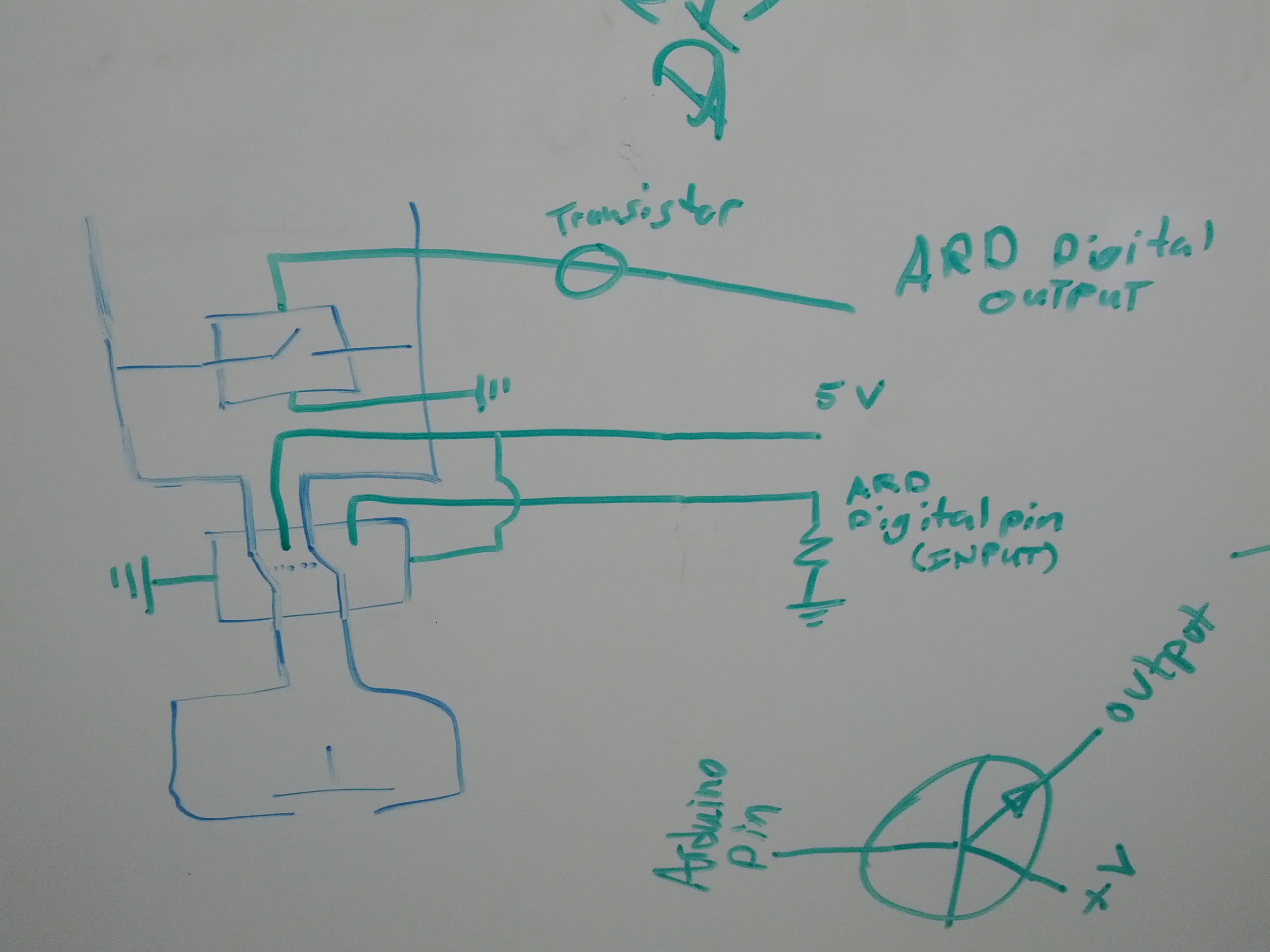
To do this, we decided to hook the power button up through a DPDT relay that is switched directly by the 5 volt supply. This way, the button is connected to the power controller when the system is off (ie. no 5 volt power is present) and then once the system is on, the button is connected to the inputs on the Arduino. Since the relay physically switches the button between circuits, it doesn’t really matter that one circuit operates at 12 volts and the other at 5.

In my schematic, I assume that the input pin on the Arduino has the internal pull up resistor activated. I also assume that the relay can be driven directly by the Arduino, which often isn’t the case. You will likely need to use a transistor to drive the relay. Note that thus far the circuit is untested and should be used at your own risk.
For those interested, my schematic is available in gschem format here.
2012
06.26
Recently I’ve been thinking about how I’d really like to make more progress on my projects and how I feel some amount of accountability would help with that. To that end, I’ve decided to start posting regular updates of my projects! Normally I like to save them up and reveal them once completed, but I think seeing feedback from readers will help to motivate me to continue moving forward on projects that might otherwise sit on the workbench for weeks, plus some people might be interested in the details of my design process (at least I might some day in the future, looking back at these posts).
To start things off, I’ll write my first progress report on my bluetooth Kinesis mod. Earlier this year I wrote about my new-to-me keyboard, the Kinesis Essential. I have a few friends who also have this style of keyboard and one of them asked me if I could convert it to bluetooth for him. We did some brainstorming, ordered some parts, and now I’m ready to start prototyping.
My friend’s Kinesis is one of the newer, USB variants. However, it turns out that the new and old boards just use a common main board and the new ones add a USB hub with an integrated PS/2 to USB converter. Since PS/2 is a pretty simple protocol, we decided to start his mod off there; a PS/2 to bluetooth converter. I later plan to replace the whole keyboard controller in my board for better battery life and mouse integration (and to further confuse people who try to use my keyboard) but that will be phase two of the project.
To get the prototype going, I’m just using an Arduino and a PS/2 socket breakout board from SparkFun. As I’ve mentioned before, I’m an avid vim user. As a vim user (and not a masochist, despite what you might know about vim), I think the Arduino programming environment is terrible, so the first thing I did was set myself up with an alternate environment in which I could stay sane. I added Arduino filetype detection to my .vimrc, found a way to build and upload code using vim’s :make command (I chose the scons method described here), and copied the PS/2 Arduino library (found here) into my project directory since the scons setup didn’t seem to find it in the default location. From there, I loaded up the example PS/2 to serial sketch and got the Arduino to read from my Kinesis! Now I need to get a simple proof of concept for my bluetooth module going and then I just need to blend the two together.
2011
10.06

Photo "borrowed" from Leif Norman (click image for source)
This past Saturday was Nuit Blanche here in Winnipeg. Some 30,000 people went around the city checking out various exhibits of art and culture. One of the exhibits at the art gallery was ARTcadia. A bunch of displays setup with indie games and hacks. I had the NES-chuck out again and it saw a lot of use. Click here for some more pictures from the WAG.
While similar to Re:Play, the core difference for this event was that the games were setup as displays rather than booths. Because of this, there wasn’t someone around to provide instructions on how to start the game (ie. how to access the start and select buttons). We had a sign up with some instructions, but few people showed any interest in reading the signs. I may have to re-evaluate how this thing works for any future public displays.
CBC was running a contest called “Culture Vulture” where you have to go to cultural events and text in the posted word for an entry. SkullSpace must be getting some attention because the keyword posted at the WAG was “hacker”.
2011
08.17
Category:
Arduino, Code, Engineering, Open Source, Projects, SkullSpace /
Tag:
code, engineering, hack, hardware, NES, video /
NES-chuck Demo from Benjamin Bergman on Vimeo.
I finally got around to making a quick demonstration of my NES-chuck. Code for the NES-chuck can be found here. The future event I mention is ArtCadia, which is part of Nuit Blanche. I’m not yet sure if I (or the NES-chuck) can attend, but I will keep this updated.
After the break, there is a rough draft of my script for the video.
Read More >>
2011
01.25
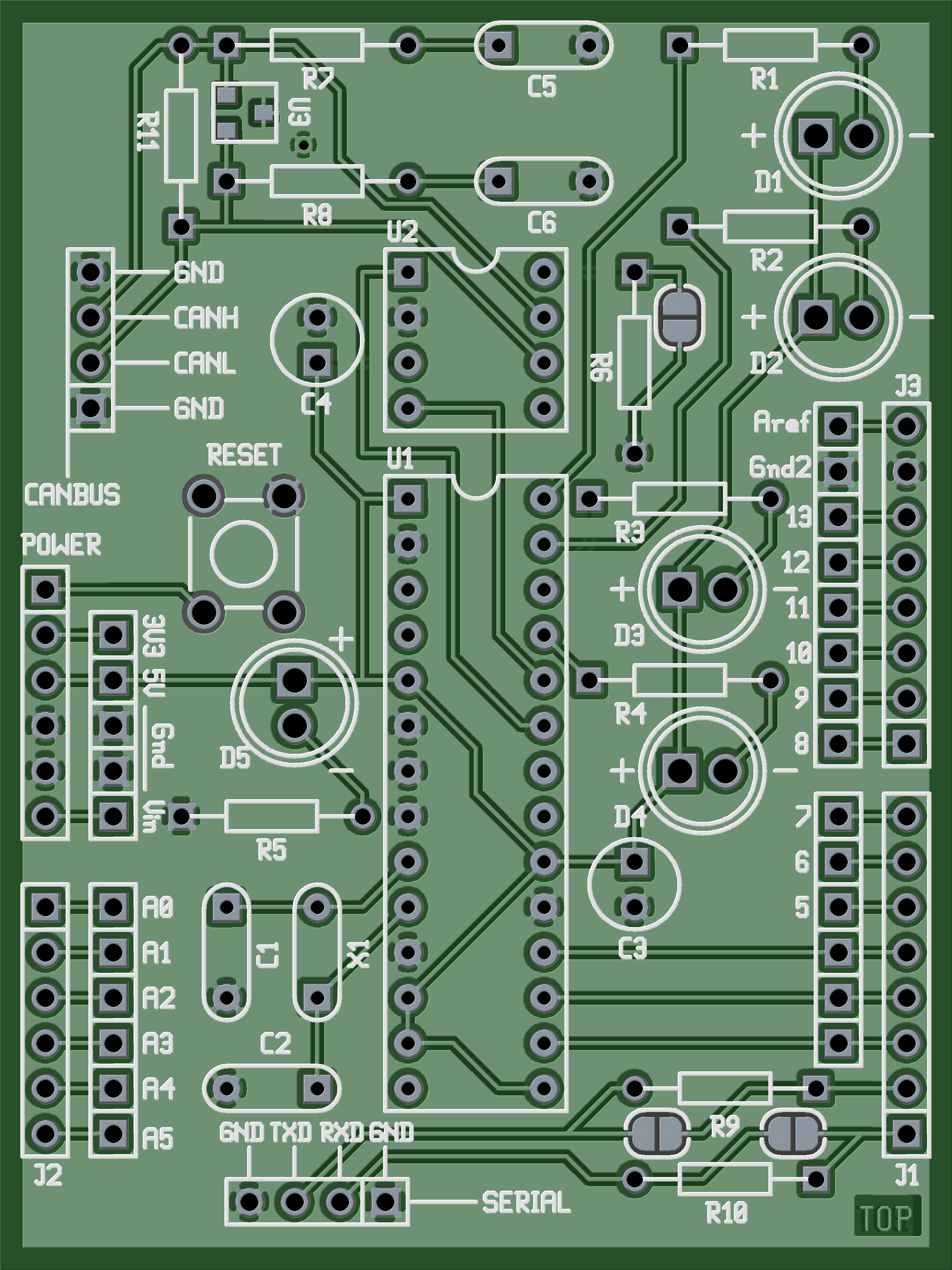
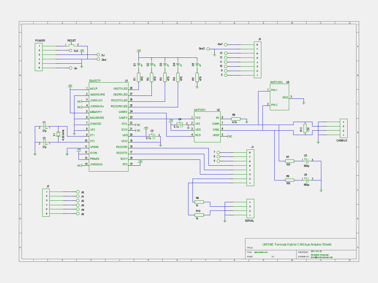
 As some of you are aware, I am a member of the University of Manitoba SAE (Society of Automotive Engineers) Formula Hybrid team. The major project that I have been working on for a while now is a CAN bus controller Arduino shield. The system is based on the one designed by Mike Sefton last year. We are using the same CAN interpreter because the manufacturer was generous enough to donate some chips to us. These chips work well, but they are designed to be used with an OBDII reader, so we are using a few work arounds to get the system to work for us the way we need.
Aside from some simple changes to the circuit, there are two major changes to the system. First, I added a the NUP2105L chip to the CAN bus to give us some over-voltage protection. The major cause of failure last year was over-voltage, which is always a concern when dealing with electric vehicles. The second change was to allow an outside system to communicate with the CAN controller over a serial connection. Last year the CAN devices were controlled directly by the Arduino, but this year the Arduino is basically a middle man that can do some processing of commands if needed.

For the hardware design, I decided to try out a few open source tools. I first tried KiCad because it was more cross platform and a fully integrated suite. There were some things I didn’t like about it though (although I may have just been looking in the wrong place for the feature I thought was missing) so I decided to try out gEDA. I personally liked the feel of gschem better than KiCad’s schematic editor, and the PCB software seemed quite good to me too. The workflow between tools is a bit less intuitive, requiring a few terminal commands, but I am quite comfortable with the command line, so I can see myself using gEDA much more in the future.
The files for the hardware design are posted here: HARDWARE
The firmware for the Arduino is posted here: FIRMWARE
The firmware is currently a very basic repeater but will likely see changes once we start figuring out what specific features we will need. Feel free to post a comment or send me an email if you have any questions about the design.


