08.18
 So a couple days ago I was tearing apart a bunch of old computers I had kicking around, pretty much just a bunch of PIIs and older. I figure they aren’t really of much value used as originally intended, but I don’t want to see them end up in a land fill or piled up in someones backyard in India, so I’m stripping them down for components for electronics projects (if anyone needs any older computer parts (including CD-ROMs, floppy drives, power supplies, sound cards, CRT monitors, etc.) or components they suspect would be on an old motherboard, feel free to drop by).
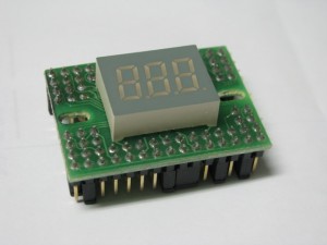
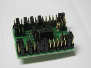
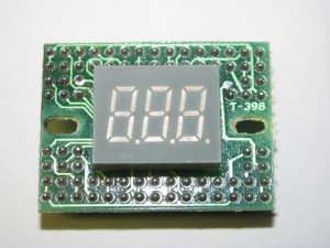
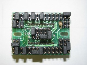
 Anyway, I pulled this one PCB out of the front of a computer that seemed a bit odd. All there is to it is a triple digit seven segment display, a single resistor (I suspect to regulate power to the display), and a huge amount of jumper pins. I think I count almost 100 pins. The thing faces out through the front of the computer case, I assume as a CPU frequency display (an older computer we used to have had a similar thing). What weirds me out is that I don’t recall there being any cable connected to this thing. I wasn’t really being too careful when disconnecting headers from the motherboards, but I really don’t recall ever unplugging this thing. Even if I had unplugged it, the majority of these pins look like they are just jumpers. There are two small 2×5 sections of pins that I suppose could have been headers for some other connector, but I don’t really see the necessity of all the jumpers.
Update: I have got the display powered up and played with the jumpers. Che out the new post.


That is really weird.
Looking at that my guess is that there are a couple of headers to connect it to the motherboard and the LCD value was set exclusively by jumpers. Now why you would use all those jumpers as opposed to either permanently wiring the LCD value or setting it based on a sensor is beyond me.
Good find!
Ya, it’s a bizarre setup. I think that they used the same case for multiple computers, but the computers they built weren’t designed to run at different clock speeds, yet competitor’s computers could and had similar readouts, so in the factory they just set these modules for the right clock of the particular computer being built. That way they just needed to get power off of the generic motherboards and not some complicated clock measurement or signal.
For posterity, the badge on the case is “Storm Systems Design.”
Yes, that’s my thoughts exactly. The thing is a gimmick, displaying the cpu frequency without actually measuring it; the SSDs are controlled by the jumpers.
You should see if you can power and control it. The resistor is probably connected to ground on one end.
I was thinking about that. I wish I could actually see the circuit better. Most of it is obscured by the SSD and the jumpers. I figure I could just put ground on one of the resistor leads and power to one of the SSD leads, but if I pick the wrong end of the resistor that could prove bad for the LEDs. Perhaps I will start with 1.5V to play it safe.